
Lorem Ipsum is simply dummy text of the printing and typesetting industry. Lorem Ipsum
has been the industry's standard dummy text ever since the 1500s, when an unknown
printer took a galley of type and scrambled it to make a type specimen book. It has
survived not only five centuries, but also the leap into electronic typesetting, remaining
essentially unchanged.


Troubleshooting the Beaver family of ultralight aircraft - Exhaust System


UltralightNews.com

Lorem Ipsum is simply dummy text of the printing and typesetting industry. Lorem
Ipsum has been the industry's standard dummy text ever since the 1500s, when an
unknown printer took a galley of type and scrambled it to make a type
specimen book. It has survived not only five centuries, but also the leap into electronic
typesetting, remaining essentially unchanged.


Beaver, Beaver ultralight aircraft, Beaver RX 35 ultralight
aircraft, Beaver RX 550 ultralight trainer troubleshooting report.
Many Beaver owners using Rotax engines have reported failure of their exhaust system.
These failures occur, along the welded seams of the exhaust or in one of the bends
going into the muffler can, or where the exhaust connects to the exhaust manifold.
These pieces can then exit into the propeller.
These are a result of poor exhaust installation. While the system must be mounted
securely, it still must be able to move on the exhaust sockets, and springs. Many
Beaver installations are to stiff, and do not allow this movement.
Rotax modified their exhaust system, to help eliminate these failures. The older two
piece exhaust manifold/exhaust has been updated to a three piece unit.
This unit consists of an exhaust Y pipe that feeds into a 90 degree elbow which fits into the exhaust. This helps prevent the build up
of harmonic vibration in the exhaust system.
Another reported problem has been with the failure of the exhaust springs. The failed
springs generally end up in the propeller. This failure is a result of improper installation
of the spring attachment points.
The springs when installed correctly should pull straight. Many infield inspections of
Beaver show that the springs are pulling at an angle and the springs are usually under too
much tension.

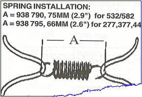
Rotax has published a bulletin giving the correct distance between these points, for each of their engine installations. Also note that
there are two different springs lengths available from Rotax depending on the engine used. Install the springs hooks at the correct
angle, and distance. Install the springs, safety wire the springs and then fill them with silicone. The silicone will absorb much of the
vibration and if the spring fails the parts will be held together by the silicone until
you can replace it.
Rotax 532 - 582 liquid cooled aircraft engines.
One of the major problems with the use of the 532 engine on the Beaver was that of
overheating. This was due to the type of radiator system used and the incorrect
placement of the water temperature sending unit. To cure the overheating problem
requires the installation of a new cooling system.
The temperature sending unit should take its temperature from the center of the
cylinder head. Another problem was with air getting trapped in the front cylinder
during climb out. This could cause an engine seizure.
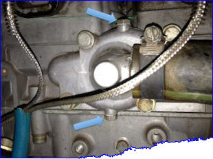
Rotax updated the 532 water pump impeller housing. This update allows air trapped in
the system to vent through the impeller housing and back into the rad system.
Another reported problem was with Rotary valve shaft and seal failure. Inner seal
failure can usually be detected by checking the colour of the oil in the Rotary valve
tank.
If a seal has failed the oil will turn a milky pink colour. Outer seal failure resulted in
coolant being discharged through a vent hole located
directly above the water pump impeller housing.
Rotax updated this area of the 532/582 by plugging
this vent hole. While this did not stop the seal
failure, it prevented coolant from escaping, allowing
the pilot to find and repair the problem.
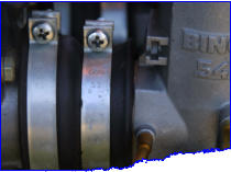
Both the 532 and 582 have had problems with intake
manifold rubbers deteriorating and failing. These
failure were reported to occur around the bolts
securing the intake rubber to the engine on the
532/582 and directly around and underneath the
securing clamps on the 532/582.
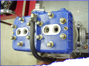



Vent line should be at highest point
during climbout.

Vent line should be at highest point
during climbout in inverted engine
installation.

