Lorem Ipsum is simply dummy text of the printing and typesetting industry
. Lorem Ipsum has been the industry's standard dummy text ever since the 1500s, when an unknown printer took a galley of type and
scrambled it to make a type specimen book. It has survived not only five centuries, but also the leap into electronic typesetting,
remaining essentially unchanged.


Troubleshooting the Beaver family of ultralight aircraft - Wing Failures!


UltralightNews.com

Lorem Ipsum is simply dummy text of the printing and typesetting industry. Lorem Ipsum
has been the industry's standard dummy text ever since the 1500s, when an unknown
printer took a galley of type and scrambled it to make a type specimen book. It has
survived not only five centuries, but also the leap into electronic typesetting, re
maining essentially unchanged.


Beaver, Beaver ultralight aircraft, Beaver RX 35 ultralight
aircraft, Beaver RX 550 ultralight trainer troubleshooting report.
Wing bracing wire failure:
Several fatalities on Beaver RX 550 have been traced to the failure of the wing bracing cable. This cable runs from one end of
the wing to the sleeve used to secure it at the strut attachment point.
It is recommended that this be an area of immediate inspection. Owner should use a nico sleeve measure tool to verify that their
nico sleeves have not elongated and were properly pressed at the factory.
According to knowledgeable people in the industry a way of fixing the problem is to disassemble the wing and replace the one
length of cable with separate cables for each wing panel securing them at each compression strut. This is not something that the
average person should attempt!
The following is based on a Transportation Safety Board of Canada - Engineering Report LP 44/93
Spectrum Beaver RX550 Incident Report:
An instructor and student were practicing stalls and stall recoveries. During a sequence, the left hand wing separated from the
aircraft, the aircraft crashed, and both occupants were fatally injured.
A detailed structural analysis was conducted. That analysis raises concerns about the use of Nicopress stop sleeves in securing
the drag truss.
Examination and Analysis.
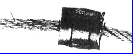
Figure 3 is a photograph of the first stop sleeve. This sleeve was loose, and could easily be moved by hand. The cable on one
side of the sleeve contained some copper coloured residue, which was considered to
have come from the sleeve, suggesting that the sleeve had previously slid along the
cable. There was also some white residue of what was considered to be teflon from
the end cap of a compression rib.
Figure 5 is a photograph comparing one of the sleeves installed by the Nicopress
manufacturer with one of the sleeves recovered from the crashed aircraft.
Comparison suggests that the sleeve from the accident aircraft was not installed
using the correct tool.
The one sleeve from the accident aircraft which had not yet slipped was also tested.
It was able to react a force of only 393 lbs. Figure 7 is a photograph of the assembly
after the test.
The mode of failure was such that there was no damage to the cable, but the sleeve


