|
http://www.ultralightnews.ca/ Page 9 of 30
The Ultralight News - your one stop Ultralight News.
2.3.The engine?s fuel system and fuel supply
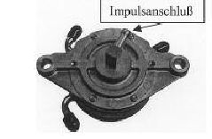
The engine?s fuel supply is provided by a Mikuni diaphragm pump (Figure 2.3-1) that is driven by pressure
pulsation from the crankcase.
Figure 2.3-1 (Fuel-diaphragm pump with impulse connection)
This diaphragm pump is positioned in the fuel line between the fuel tank and Bing carburettor(s). A fuel filter
should always be installed between the fuel pump and fuel tank.
The Mikuni fuel pump should be secured to a location with the least influence of vibration or heat. It is
important that it is installed upright with the fuel outlet at the top. The assignment of the fuel connection
direction can be identified on the housing by arrows.
The central connection of the Mikuni pump is connected to the vacuum impulse line from the crankcase and
should be as short and straight as possible. When choosing the impulse line and the fuel line it is important to
ensure that rigid lines are used and do not expand under pressure. The impulse line should not exceed a
maximum length of 150mm with a minimum inner diameter of 6 mm.
The positioning of the fuel tank over the engine is advantageous as would ensure a reasonable fuel supply
pressure. It is recommended to maintain a constant fuel pressure under all conditions, the fuel should be
installed as well. Additional monitoring of fuel pressure by means of a fuel pressure gauge may also be
considered.
When installing the fuel tank beneath the engine, the maximum fuel line length between the fuel tank and
diaphragm pump should not exceed 2,000mm. The maximum suction head should not exceed 1,000m with a
minimum inner diameter of 6mm.
Be aware of the possible gradient of the vehicle the engine is installed in during operation i.e. ascent-/descent
with aircraft, uphill-/downhill with ground vehicles.
The maximum length of the fuel outlet pressure line should not exceed 500 mm with a minimum inner
diameter of 6 mm. A maximum pressure head between the centre of the diaphragm pump and centre of the
carburettor float chamber may not be exceeded.
If a Mikuni pump is installed on the engine, it is recommended the diaphragm of the pump stands vertical to
the crankshaft axis (drive or ignition side ). This will ensure that resonance produced by the crankshaft axis
from the engine does not impair the action and function of the fuel pump.
2.4.The operation of dual carburettors
The throttle valves of the Bing carburettors are operated via two Bowden type cables. It is advantageous to
run both cables from the throttle into a single cable by means of a Y-shunt or cable splitter.
If at all possible, both throttle cables between the Y-shunt and the carburettors should be the same length.
In idling position (both throttle valves sit on the idle ? adjusting screw) there should still be enough play in
the throttle cable to ensure that the throttle valves can reach the idle position stop.
|
|