|
http://www.ultralightnews.ca/ Page 8 of 30
The Ultralight News - your one stop Ultralight News.
2.Installation instructions
2.1.Mounting and securing the engine
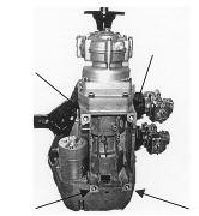
The four screw threads (UNC- ½?) on engine 2706 for the fastening of the engine are located on the
underside of the crankcase.
Figure 2.1-1(Fastening thread points)
The engine should be mounted so that the moment from the engine to the mounts can be absorbed as widely
as possible. The absorbing of the mounts should also be made as hard as possible, since the engine can
become unstable if the absorbing mounts are too soft. This leads to problems within the carburettors fuel
bowl as well as uncontrolled vibration of the fuel pump diaphragm, intimating to an unsafe operation of the
engine.
-Suggestion for securing the engine:
The engine is secured to a fastening plate that is about twice the width of the engine (the wider the better).
On the two outer surfaces of the fastening plate six (or more) hard rubber absorber elements (three on each
side) are attached in an axial direction. This complete substructure is secured by the rubber absorber
elements on to a corresponding base plate.
2.2.The engine?s air supply
The engine must be installed so the cooling air stream fed to the engine is sufficient to ensure the engine is
cooled and that air is also supplied to the carburettors.
With an enclosed installation it is important that the hot outlet air stream is not fed to the carburettors, as this
leads to a drastic reduction in performance. It is also important to ensure that the hot outlet airstream can
escape with out hindrance from the metal cladding, since this leads to overheating of the engine and also
damage.
The ducted cooling system fixed to the motor is designed so that adequate supply of fresh air for cooling of
the engine is sufficient. Changes to the cooling system therefore are not recommended. It is essential to
ensure that a sufficient supply of air is provided at all times during operation.
|
|