|
http://www.ultralightnews.ca/ Page 7 of 36
The Ultralight News - your one stop Ultralight News.
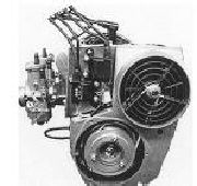
Figure 1.3-3
(View of ignition side with installed ignition system)
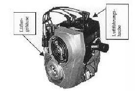
1.4Description of the cooling system
The 2706E engine has a mechanically operated forced fan cooling system. (Figure 1.4-1).
The fan wheel is installed in the fan housing. It is driven by a flat belt and a pulley that is fixed to the
ignition system?s magnetic flywheel. A stream of cool air generated by the fan is distributed for optimal
cooling to the two cylinders. The hot air stream from the cooling system is blown off to the opposite side of
the engine into the surroundings on the intake side.
Figure 1.4-1 (View of the fan housing and the air conduction cowl)
1.5The engine?s fuel injection components
Throttle body injection (TBI): (Figure 1.5-1 Position 17)
Function: Performance regulator of the engine through operation of the throttle body.
The TBI consists of the following main components:
a)Throttle position sensor (potentiometer) (Figure 1.5-1 Position 22)
Function: To electronically transmit the angle of the throttle valve to the Injection system.
b)Injector valves (Figure 1.5-1 Position 18)
Function: Dosage and atomisation of fuel.
c)Throttle cable and bell crank (Figure 1.5-1 Position 23; 23a; 23b)
Function: Throttle cable housing and the adjustment of the off idle motion of bell crank as well as
attachment of throttle cable and idle adjustment.
d)Pressure regulator and pressure regulator housing. (Figure 1.5-1 Position 24 & 27)
Function: maintains 42 PSI fuel pressure to the injectors.
|
|