http://www.ultralightnews.ca/ Page 11 of 36
The Ultralight News - your one stop Ultralight News.
2Installation instructions
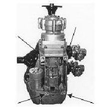
2.1Mounting and securing the engine
The four screw threads (UNC- ½?) on the 2706E engine for fastening the engine are located on the underside
of the crankcase.
Figure 2.1-1(Fastening thread points)
The engine should be mounted so that the moment from the engine to the mounts can be absorbed as widely
as possible. The absorbing of the mounts should also be made as hard as possible, since the engine can
become unstable if the absorbing mounts are too soft. This leads to problems within the carburettors fuel
bowl as well as uncontrolled vibration of the fuel pump diaphragm, intimating to an unsafe operation of the
engine.
-Suggestion for securing the engine:
The engine is secured to a fastening plate that is about twice the width of the engine (the wider the better).
On the two outer surfaces of the fastening plate six (or more) hard rubber absorber elements (three on each
side) are attached in an axial direction. This complete substructure is secured by the rubber absorber
elements on to a corresponding base plate.
2.2Fuel Injection Electrical installation:
The 12 Volt power supply is to be connected separately. Between the battery and the computer, there cannot
be any other electrical components (consumer) connected within this part of the circuit. The wire harness is
to be installed in a way where the electrical cable cannot touch the ground during operation.
The cable must be secured to avoid any wear or breakage from vibration etc..
The control unit must not be exposed to water. All other electrical components are reasonably waterproof.
The control unit must be installed in an area where the barometric air pressure sensor (nipple protruding from
side of computer) cannot be influenced by air turbulence. This barometric air pressure connector cannot be
sealed off (rubber caps etc.).
The electrical components cannot exceed an operation temperature of 80 degree Celsius, 176 degree
Fahrenheit. (Short period maximum exposure of 100C, 212F). The wire harness has to be installed with a
sufficient enough distance from all other electrical wires to prevent electromagnetic interference of the sensor
and computer wires of the injection system.
The required wire diagram and applicable fuses are shown in the circuit diagram on page 36.
