http://www.ultralightnews.ca/hirth-engines.htm Page 5 of 31
The Ultralight News
1Description of the Engine, Mounting Instructions and Technical Data
1.1Overview
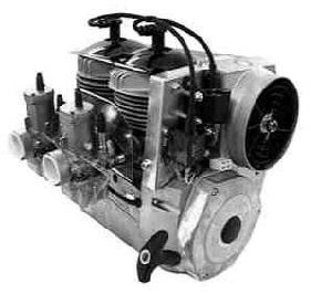
The 2704 engine (Figure 1.1.1-1) of Göbler-Hirthmotoren KG is a two cylinder in-line two-stroke engine
available with a ducted cooling system or a free air ducted cooling system.
The cylinders consist of an aluminium alloy with a Nikasil coated running surface that is highly resistant to
wear. The cylinders are mounted onto the crankcase by stud bolts, discs and hexagon nuts. The cylinder
heads consist of a special hypereutectic aluminium alloy that resists high temperatures while maintaining
constant hardness. They are secured onto the cylinder by means of cylinder screws and washer without using
agasket to assist cooling.
The pistons consist of an aluminium alloy and are sealed off from the cylinder running surface by two piston
rings. The piston is connected to the con-rod by the gudgeon pin and a needle bearing.
The crankshaft is made of chrome-molybdenum steel (42 Cr Mo 4) and is mounted in five deep groove ball
bearings. It?s really an assembled crankshaft and the individual parts of the crankshaft are pressed together to
form a complete unit. Two deep groove ball bearings are installed on the drive side, two between the con-
rods and one on the ignition side. The drive shaft is tapered and has a centred thread in order to secure to the
PTO shaft. The con-rods are connected to the crankshaft by crank pins and needle bearings.
The crankcase consists of an aluminium alloy and constructed as a case in two halves. It is secured together
by seven bolts and eight fastening studs and nuts which secure the cylinders to the case. Opposite the PTO
end of the crankcase, there is an ignition stator unit. This is fixed to the crankcase and is concealed by the
flywheel and the fan housing..
Figure 1.1.1-1 (Engine 2704)
1.2Description of the carburation system
The carburation system (Figure 1.1.2-1) of the 2704 engine consists of one or two Bing carburettors. Each
carburettor is connected to the inlet aperture of the cylinder by a rubber flange and is secured to the inlet
aperture by means of a clamp held in a rubber flange. They are thermally neutralised from each cylinder by
an insulating plate thereby shielding the carburettors from the hot air exiting from the cooling system. The
carburettors have a dry air filters installed.
