  Operator's Manual
Engine
F30E
Göbler-Hirthmotoren KG, Max-Eyth-Str. 10, D-71726 Benningen
Tel.: 07144-8551-0, Fax: 07144-5415
Distributed by AATI Pty Ltd, Aircraft & Agricultural Tillage Importers
e-mail: info@aati.com.au, internet: http://www.ultralightnews.ca/
Phone Australia: (07)5464-4993, Fax: (07)5464-4995
Phone International: +61 7 5464-4993, Fax +61 7 5464-4995
|
 Operator's Manual
Engine
Model F30E
Read this operator's manual thoroughly before putting the engine into operation for the first time and comply
strictly with the instructions given here.
In the interests of continual development of our engines we must reserve the right to change conditions of
delivery for design, engineering and fixtures. We also request your understanding that no claims can be made
against statements and Figures from this manual.
THIS ENGINE DOES NOT COMPLY WITH FEDERAL SAFETY REGULATIONS FOR
STANDARD AIRCRAFT. THIS ENGINE CAN BE USED IN EXPERIMENTAL AND ULTRA-
LIGHT UNCERTIFIED AIRCRAFT ONLY IN CIRCUMSTANCES WHICH AN ENGINE FAILURE
WILL NOT COMPROMISE SAFETY. BEFORE OPERATING THE ENGINE READ OPERATOR'S
MANUAL INFORMATION AVAILABLE FROM YOUR AUTHORISED HIRTH DISTRIBUTOR.
Göbler-Hirthmotoren KG
|
 1Description of the Engine, Mounting Instructions and Technical Data.....................................................5
1.1 Overview...........................................................................................................................................5
1.2 Description of the fuel injection system.............................................................................................5
The engine?s fuel injection components....................................................................................................6
1.3 Description of the Ignition System....................................................................................................9
1.4 Description of the cooling system....................................................................................................10
2Installation instructions............................................................................................................................11
2.1 Mounting and securing the engine...................................................................................................11
2.2 The engine?s air supply....................................................................................................................11
2.3 Fuel Injection Electrical installation:...............................................................................................11
2.4 Hydraulic Installation:.....................................................................................................................11
2.5 Fuel injection wiring installation.....................................................................................................12
Additional precautionary steps to avoid fuel injection failure.................................................................13
Additional steps for a more efficient engine operation:...........................................................................13
3Monitoring Apparatus..............................................................................................................................14
3.1 Cylinder head temperature...............................................................................................................14
3.2 Exhaust gas temperature..................................................................................................................15
3.3 Fuel Pressure...................................................................................................................................16
3.4 Model Identification plate...............................................................................................................17
4Specifications ? F30E engine..................................................................................................................17
4.1 Installation Drawing - F30E............................................................................................................18
5Exhaust System........................................................................................................................................19
5.1 Exhaust parts and measurements.....................................................................................................20
6Operation of the Engine...........................................................................................................................21
6.1 General............................................................................................................................................21
6.2 Running in - Recommendation........................................................................................................21
6.3 Initial Inspection..............................................................................................................................21
6.4 Starting Procedure...........................................................................................................................22
First time in operation:............................................................................................................................22
6.5 Starting the engine...........................................................................................................................22
Cold engine..............................................................................................................................................22
6.6 Operating condition of the engine....................................................................................................23
Hot engine...............................................................................................................................................23
6.7 Shut down the engine.......................................................................................................................23
6.8 Adjustments.....................................................................................................................................23
6.9 Starting Procedure...........................................................................................................................24
6.10 Operating condition of the engine................................................................................................24
6.11 Powering down the engine...........................................................................................................25
7Maintenance............................................................................................................................................26
7.1 General............................................................................................................................................26
7.2 Tools, special tools and torques.......................................................................................................26
7.3 Maintenance rate - Daily inspections...............................................................................................27
7.4 Fuel Injector Maintenance/Service intervals....................................................................................28
The following parts must be replaced......................................................................................................28
Long-term inspections.............................................................................................................................28
8Replacement of Parts...............................................................................................................................29
8.1 Inspecting the air filters...................................................................................................................29
8.2 Inspecting the fuel lines...................................................................................................................29
8.3 Inspecting pulsation lines.................................................................................................................29
8.4 Spark plugs and sparkplug leads......................................................................................................29
8.5 Inspecting the condition of the sparkplug leads...............................................................................29
8.6 Installing and removing sparkplugs.................................................................................................30
8.7 Condition of the sparkplug..............................................................................................................30
9Fans.........................................................................................................................................................30
9.1 Remove and assembling the air cowl...............................................................................................30
9.2 Remove and assembling the fan housing.........................................................................................30
10 Cylinder head...................................................................................................................................30
10.1 Cylinder head removal and installation.......................................................................................30
10.2 Checking the condition of the cylinder head................................................................................31
|
|
11 Trouble Shooting (general)..............................................................................................................32
11.1 Engine Does Not Start or is Difficult to Start..............................................................................32
11.2 Engine Runs Rough, Uneven, and with Insufficient Power.........................................................32
11.3 Excessive Cylinder Head Temperature........................................................................................32
12 Wiring Diagrams.............................................................................................................................33
12.1 Single PVL Ignition system - F30E.............................................................................................34
12.2 Dual PVL ignition system ? F30E...............................................................................................35
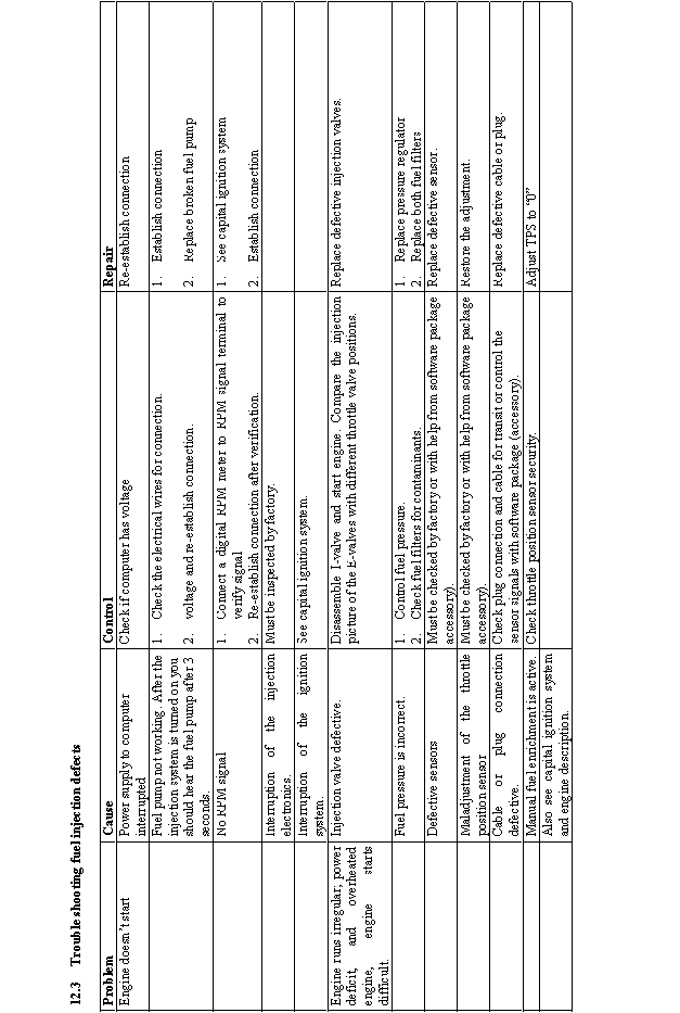
12.3 Trouble shooting fuel injection defects........................................................................................36
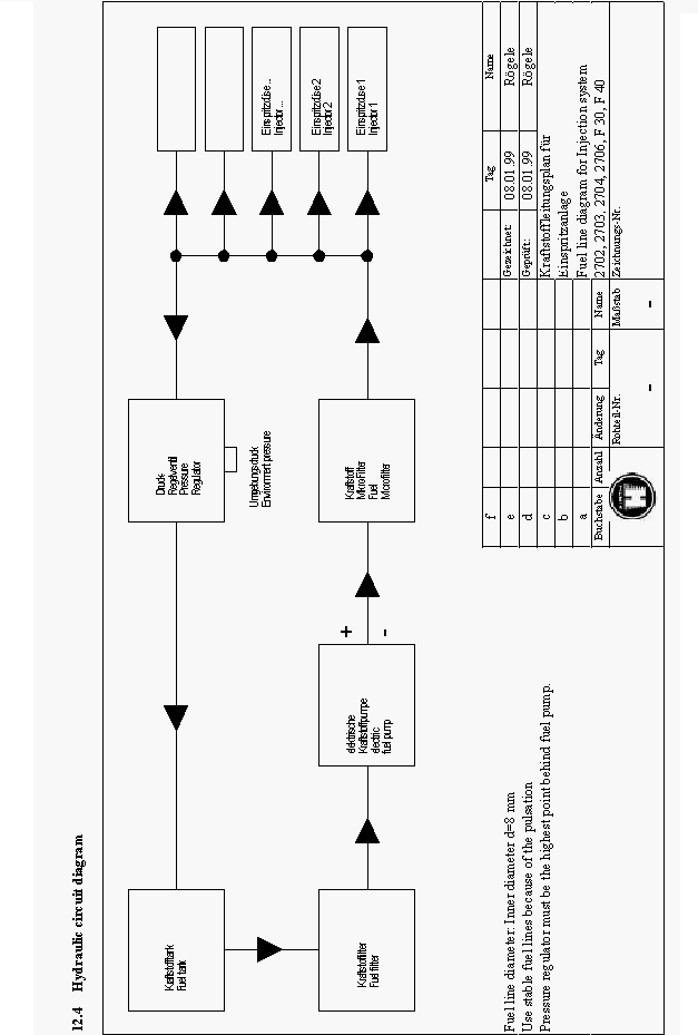
12.4 Hydraulic circuit diagram............................................................................................................37
12.5 Electrical circuit diagram.............................................................................................................38
|
 http://www.ultralightnews.ca/ Page 5 of 39
The Ultralight News - your one stop Ultralight News.
1Description of the Engine, Mounting Instructions and Technical Data
1.1Overview
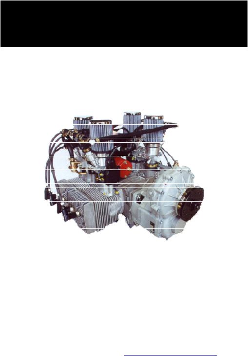
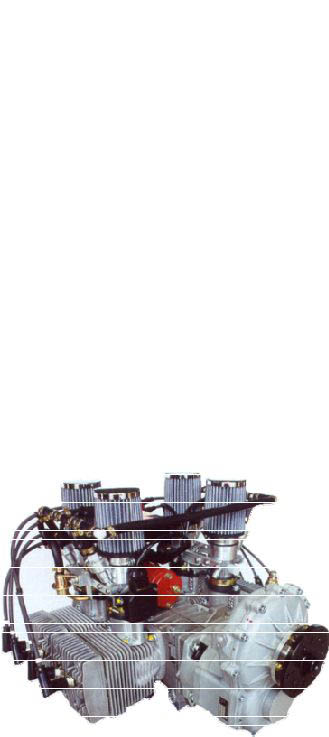
The F30E engine (Figure 1.1.1) of Göbler-Hirthmotoren KG is a piston ported four-cylinder boxer two-
stroke engine that is available both as a free-air and a fan-cooled engine.
The cylinders consist of an aluminium alloy with a Nikasil coated running surface that is highly resistant to
wear. The cylinders are mounted onto the crankcase by stud bolts, discs and hexagon nuts. The cylinder
heads consist of a special hypereutectic aluminium alloy that resists high temperatures while maintaining
constant hardness. They are secured onto the cylinder by means of cylinder screws and washer without using
agasket to assist cooling.
The pistons consist of an aluminium alloy and are sealed off from the cylinder running surface by two piston
rings. The piston is connected to the con-rod by the gudgeon pin and a needle bearing.
The crankshaft is made of chrome-molybdenum steel (42 Cr Mo 4) and is mounted in five deep groove ball
bearings. It?s really an assembled crankshaft and the individual parts of the crankshaft are pressed together to
form a complete unit. Two deep groove ball bearings are installed on the drive side, two between the con-
rods and one on the ignition side. The drive shaft is tapered and has a centred thread in order to secure to the
PTO shaft. The con-rods are connected to the crankshaft by crank pins and needle bearings.
The crankcase consists of an aluminium alloy and constructed as a case in two halves. It is secured together
by fastening studs and nuts which also secure the cylinders to the case. Opposite the PTO end of the
crankcase, there is an ignition stator unit. This is fixed to the crankcase and is concealed by the flywheel and
the fan housing..
Figure 1.1-1 (Engine F30E)
1.2Description of the fuel injection system
The applied fuel injection system is a sequential multi-point fuel injection. The throttle body injection is
installed in place of carburettors. Both throttle body injection (TBI) units are connected at the bell crank and
are synchronised with each other through the throttle body shaft.
The fuel pressure is provided by a Pierburg electric fuel pump and maintains 42 Lbs. PSI. This stays
consistent with the help of a pressure regulator. To avoid interruption from contaminated fuel, a series of fuel
filters are installed fore and aft of the fuel pump.
|
 http://www.ultralightnews.ca/ Page 6 of 39
The Ultralight News - your one stop Ultralight News.
The amount of fuel is controlled through the injector nozzle (governed by the throttle position-RPM). The
dosage is refined through different adjustment parameters. The following parameters are used for the
calculation of fuel ratio-amount of injection:
Throttle position
RPM
Ambient air temperature
Barometric pressure
Engine crankcase temperature
Acceleration rate
Manual manipulation (optional)
The engine?s fuel injection components
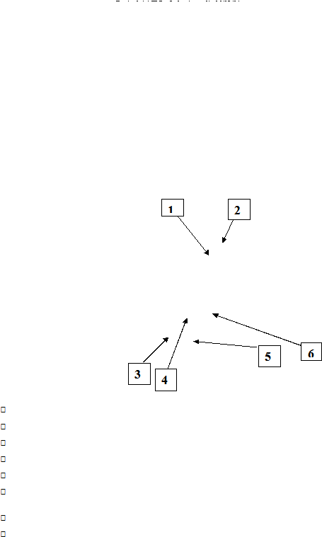
Throttle body injection (TBI): (Figure 1.2-1 Position 17)
Function: Performance regulator of the engine through operation of the throttle body.
The TBI consists of the following main components:
a)Throttle position sensor (potentiometer) (Figure 1.2-1 Position 22)
Function: To electronically transmit the analogue angle of the throttle valve to the Injection system.
b)Injector valves (Figure 1.2-1 Position 18)
Function: Dosage and atomisation of fuel.
c)Throttle cable and bell crank (Figure 1.2-1 Position 23; 23a; 23b)
Function: Throttle cable housing and the adjustment of the off idle motion of bell crank as well as
attachment of throttle cable and idle adjustment.
d)Pressure regulator and pressure regulator housing. (Figure 1.2-1 Position 24 & 27)
Function: maintains 42 PSI fuel pressure to the injectors.
|
  http://www.ultralightnews.ca/ Page 7 of 39
The Ultralight News - your one stop Ultralight News.
Figure 1.2-1: Throttle body injector (TBI)
Fuel pump/filters
Function: To filter the fuel and to produce the injection system pressure.
The fuel pump/filter units consist of the following main components:
a)Fuel filters (Figure 1.2.2 Position 3)
Function: To protect fuel pump from pollutants greater than 10 microns.
b)Fuel pump (Figure 1.2.2 Position 3)
Function: To produce the system pressure and deliver fuel to the injection valve.
Warning Only connect the fuel pump power supply through ignition switch power supply
Fuel Filter (Figure 1.2.2 Position 2) Function: Protect the injector valves from pollutants
greater than 1 microns
|
  http://www.ultralightnews.ca/ Page 8 of 39
The Ultralight News - your one stop Ultralight News.
Figure 1.2.2: Fuel filter units
Wire harness (Figure 1.2-3 Position 2)
Function: Electrical connection between the sensors/actuators and the computer power supply.
The wire harness consists of the following components:
Sensor/sensor connectors:
a)Air temperature sensor
b)Crankcase temperature sensor
c)Plug connector to throttle position sensor.
d)RPM connector
Actuator connectors:
a)Injector valve power supply
b)Fuel pump power supply
Other connectors:
a)Computer power supply connector
b)Power supply 12 Volt
Control Unit (Red box) (Figure 1.2-3 Position 1)
Function: Processing of data from sensors. Power supply to the injector valves, the fuel pump, and
houses the barometric sensor.
The control unit consists of the following main components:
a)Plug connector
b)Barometric pressure connector
Features: On the side of the control unit is a sticker with the number of the software.
Example (F30-44) Engine type-F30, version-44.
|
  http://www.ultralightnews.ca/ Page 9 of 39
The Ultralight News - your one stop Ultralight News.
Figure 1.2-3: Wire harness with control unit
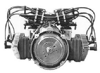
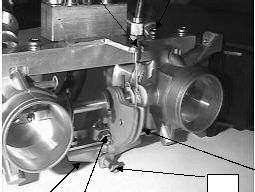
1.3Description of the Ignition System
The ignition system (Figure 1.3-3) consists of a armature plate, a magneto, E-Box(s), ignition coils and the
ignition cables with the required number of spark plug leads. The ignition system is completely electronic
and possesses an E-PROM for a freely programmable ignition curve however, this can only be carried out by
the manufacturer. Alternating Current (AC) power for electrical components during running and charging of
the battery is provided. The engine is available with a single or dual ignition system installed.
An electronic stator plate is secured on the ignition side with the crankcase. A magneto is fixed on the
crankshaft and encloses the armature plate. The fan housing covers the ignition system?s magnetic wheel.
The electronic E-box and ignition coils are mounted on a fixture plate secured to the crankcase as shown in
figure 1.3.3.
|
  http://www.ultralightnews.ca/ Page 10 of 39
The Ultralight News - your one stop Ultralight News.
Figure 1.3-3
(View of ignition side with installed ignition system)
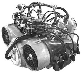
1.4Description of the cooling system
The F30E engine has a mechanically operated forced fan cooling system. (Figure 1.4-1).
The F30E engine has the option of mechanically driven fan-ducted cooling fixed to the ignition side (Figure
1.4-1). The cooling fans are installed in the fan housing by eccentrics. They are driven by a poly flex belts
and a pulley that is fixed to the ignition system?s magnetic wheel. The cool air forced by the cooling fans is
distributed for optimal cooling of the cylinders by the air cowls that cover the two cylinders on each side of
the engine. The hot air from the cooling system is blown off to the underside of the engine.
Figure 1.4-1 (View of the fan housing and the air conduction cowls)
The F30E engine is also run as a free-air engine. During installation it is important to ensure that the cooling
air produced by the propeller or free air provides adequate cooling to all cylinders. If this is not the case,
then air cowls providing correct cooling and suits the particular application must be fitted to the cylinder
heads
|
 http://www.ultralightnews.ca/ Page 11 of 39
The Ultralight News - your one stop Ultralight News.
2Installation instructions
2.1Mounting and securing the engine
The F30E engine has twelve securing points with threads (M10) that can be used for securing the engine.
There are in each case four screw threads on the underside, on the left and the right housing side of the
engine.
The engine should be secured in such a way that the force transferred from the engine to the suspension can
be absorbed as widely as possible. Suspension absorption should also be made as hard as possible, since the
engine can become unstable if absorption is too soft. This leads to problems for the carburation (frothing of
fuel, uncontrolled vibration of the fuel pump diaphragm) and thus to an unsafe operation of the engine.
-Suggestion for securing the engine:
The engine is screwed to a fastening plate that is about twice as wide as the underside of the engine (the
wider the better). On the two outer surfaces of the fastening plate six (or more) hard rubber absorber
elements (three on each side) are attached in an axial direction. This complete substructure is secured by the
rubber absorber elements on to a corresponding base plate that is firmly connected to the device.
2.2The engine?s air supply
The engine must be installed so the cooling air stream fed to the engine is sufficient to ensure the engine is
cooled and that air is also supplied to the carburettors.
With an enclosed installation it is important that the hot outlet air stream is not fed to the carburettors, as this
leads to a drastic reduction in performance. It is also important to ensure that the hot outlet airstream can
escape with out hindrance from the metal cladding, since this leads to overheating of the engine and also
damage.
The ducted cooling system fixed to the motor is designed so that adequate supply of fresh air for cooling of
the engine is sufficient. Changes to the cooling system therefore are not recommended. It is essential to
ensure that a sufficient supply of air is provided at all times during operation.
2.3Fuel Injection Electrical installation:
The 12 Volt power supply has to be connected separate, which means between the battery and the
computer there cannot be any other electrical components (consumer) connected to it.
The wire harness is to be installed in a way where the electrical cable cannot touch any ground
during operation.
The cable has to be installed in such a way that no chance of wear or breakage could occur.
The control unit must not be exposed to water. All other electrical components are waterproof.
The control unit has to be installed in an area where the air pressure sensor (nipple protruding from
side of computer) cannot be influenced by turbulent air.
This air pressure connector cannot be sealed off (rubber caps etc.).
The electrical components cannot exceed an operation temperature of 80 degree Celsius, 176 degree
Fahrenheit. (Short time maximum exposure of 100C, 212F).
The wire harness has to be installed with a sufficient enough distance from all other electrical wires
to prevent electromagnetic interference of the sensor and computer wires of the injection system.
The required wire diagram and applicable fuses are shown in the circuit diagram on page 35.
2.4Hydraulic Installation:
The maximum suction height for the electric fuel pump is 500mm or 19 inches. (Also pay close
attention to extreme flying position ie. take off).
The fuel pump should be installed close by the fuel tank, so the suction pipe stays short. The supply
has to be dimensional where the fuel pump can suck in a minimum of 120 L/H. (Recommended pipe
diameter minimum 10mm or 0.39 inches).
|
 http://www.ultralightnews.ca/ Page 12 of 39
The Ultralight News - your one stop Ultralight News.
All fuel-carrying components have to be installed with enough distance from any hot component to
prevent danger from fuel ignition or explosion. (ie. exhaust system).
Each fuel line has to have a pipe clamp installed for security. The fuel lines between the fuel filters
and the engine must be made of fuel durable material and resist a pressure of min. 6 bar.
The fuel return line to the fuel tank must have a diameter of 8mm or 0.312 inches to prevent back
pressure.
With a dual fuel tank system you must pay close attention that both fuel tanks are connected to each
other in such a way that uneven fuel levels do not occur from fuel return.
On dual fuel tanks which are controlled separately, you must have an overflow connection installed,
or it must have a fuel return valve that will direct fuel to the tank that is in operation so as not to
deplete operational fuel tank or create an overflow situation.
2.5Fuel injection wiring installation
1.Install the engine according to the installation instruction.
2.Install the computer at a suitable place (pay attention to the length of the wire harness)
3.Install the wire harness according to the above-mentioned connections and connect the blue plug to the
computer.
Note: The blue plug can only be connected in one position with the computer.
4.Connect the power supply (red +) with the on/off switch. The supply line to the switch has to be installed
according to the above mentioned instructions. Connect the power supply ground (black -) to a ground
or even better, directly to the (-) negative pole on the battery.
5.Install the fuel pump (close by the fuel tank), and lay the pressure line from the fuel filter to the engine.
Secure them with the pipe clamps (Figure connection to the engine-connection to the filter).
6.Connect the supply line from the fuel tank to the suction connection of the fuel pump/fuel filter (big pipe
connection) and secure them with the pipe clamps.
7.Secure the relay supplied to a suitable location within close proximity of the fuel pump
8.The green and black wires from the harness are connected to the location points 85 and 86 of the relay.
9.Connect the positive (+) separate line from the switch to the location point 30 of the relay.
10.Connect from the location point 87 of the relay to the positive (+) connection on the fuel pump.
11.Connect from the negative (-) of the fuel pump to a negative (-) point of the battery. Please ensure all
connections are suitable for at least 8 Amp?s
12.Hook the throttle cable to the bell crank of the TBI (Figure 2.5-1 Position 5), page 22. Adjust the throttle
cable with the adjusting screw (Figure 2.5-1 Position 2) so that the throttle cable in the idle position has
some play (2-4mm or 0.078-0.156 inches) and secure with the locknut (Figure 2.5-1 Position 1). Make
sure that the idle stop (Figure 2.5-1 Position 5) nut is adjacent to the throttle stop (Figure 2.5-1 Position
3).
13.Synchronisation of the throttle control
Open the throttle a short way and take care the space between the throttle and the throttle body is the
same width at both throttle bodies. Use a round object for that. Fix the throttle in a position where the
round object has the same diameter than the width of the crack. Check for the same distance on the
opposite throttle body. Adjust accordingly. When the throttle is set to the idle position, both throttle
adjustment screws must contact the throttle stop. Allow only a small amount of play in the throttle cable.
|
|
http://www.ultralightnews.ca/ Page 13 of 39
The Ultralight News - your one stop Ultralight News.
14.Function testing:
Turn on the fuel injection system (without starting the engine). In doing so the fuel pump must run 3-8
seconds. Open the throttle valves completely. By doing so you must clearly hear a rattling noise from the
injector valves for approximately 1 second in duration.
15.After repeated openings and closing of the throttle you need to check the gasket of the fuel hydraulic
while the system is turned on.
Additional precautionary steps to avoid fuel injection failure
The following steps are worth consideration and may assist to avoid interruption by the fuel injection system.
1.An additional parallel fuel pump, with the required fuel filters that can be switched manually should the
main fuel pump fail.
2.To avoid interruption of the RPM signal. The signal line of the injection system must be connected
separately to the ignition system and not to an additional RPM tachometer (factory installed). If there is
an interruption caused by a tachometer, the RPM signal could affect the signal to the computer.
Recommendation: Use an inductive tachometer, which gathers RPM pulses from the spark plug wires.
3.Control of the fuel injection system:
To avoid interruptions of the hydraulic system early, the fuel pressure should be monitored regually. It
would be also recommended to monitor the voltage and power supply to the injection system.
In case of defective regulators or a defective consumer component the battery voltage will slowly reduce
(battery discharge). This can be detected early and through proper measurements (turn off all consumers
not necessary for the primary operation). The operation time can be prolonged as the minimum voltage
necessary to operate the fuel injection system is 10 Volts.
4.Power supply control:
Should, due to a damaged electrical component (injection valves, fuel pump) the power supply increase,
you can detect this early through measuring the amperage.
Additional steps for a more efficient engine operation:
1.Ram Air Box
When operating in tractor configuration in an uncertified aircraft, you can use the airstreams and the
developing back pressure in a ram air box to ?charge? the engine. To avoid unnecessary leanness of the
air/fuel mixture, you must have a hose connection from the computer barometric pressure sensor to the
ram air box so the computer can compensate for the increase in air pressure.
2.Manual fuel enrichment (accessory)
Allows manual increase of fuel to normal program parameters. This would be used to enrich the fuel
mixture to cool the engine in special applications only. In normal engine operations this accessory is not
used.
1.Computer interface and RS232 interface hardware.
With the software you can monitor the sensors and the return signal of the injection system. Beyond that
you can download new programs to the control unit. These updates are available through authorised
Hirth distributors or Göbler-Hirthmotoren via the Internet. With that, you will always have the latest
software update.
|
  http://www.ultralightnews.ca/ Page 14 of 39
The Ultralight News - your one stop Ultralight News.
3Monitoring Apparatus
It is recommended that the cylinder head temperatures, the exhaust gas temperature and the fuel pressure be
monitored.
The basic setting of the engine guarantees a problem free-engine function under the general installation
conditions. It is very important for safe running of the engine that the cylinder head, exhaust gas temperature
and the fuel pressure are monitored.
The equipment listed in Table 3-1 can be purchased from AATI Pty Ltd.
Table 3-1
Description Part No.
Westach Exhaust gas temperature measuring device (2x, as a set) 029.30
Westach Cylinder head temperature measuring device (2x,as a set) sparkplug 14 mm 029.31
Westach Cylinder head temperature measuring device(2x, complete) sparkplug 10 mm 029.32
Westach Fuel pressure measuring device 029.20
Westach Tachometer 029.14
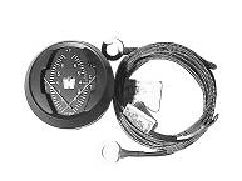
3.1Cylinder head temperature
To allow for expansion of the piston in an air cooled engine, the tolerance between the piston and the
cylinder wall is essential for expansion and contraction. As the piston and cylinder heat under normal
operating conditions they expand, the piston becomes "larger" while at the same time the cylinder walls
expands. Engine manufactures allow for this "expansion" and "contraction" when they produce the engine.
Normally a Hirth air cooled engine should read between 350F to 410F on a cylinder head temperature gauge
(CHT). When an engine overheats the amount of expansion between these parts is greater than allowed - the
piston becomes too tight in the cylinder and the piston "seizes' creating permanent damage to the piston and
or cylinder wall
Figure 3.1 Dual Westach CHT 029.31/029.32
AWestach CHT (Figure 3.1) gauge uses a Type K thermocouple, which requires no power. The
thermocouple produces a small voltage which to work properly requires good continuity to reach the
instrument
The thermocouple, which is available in two different sizes depending on the spark plug used - is mounted
under the spark plug, and replaces the spark plug washer.All of the Hirth two cylinderengines use a
10mm or a 14mm probe.
|
  http://www.ultralightnews.ca/ Page 15 of 39
The Ultralight News - your one stop Ultralight News.
CHT temperatures in excess of 280°C or 536°F are a result of :
Lack of oil in fuel or NO oil in the fuel.
Poor piston cylinder lubrication, due to poor quality of oil.
The use of a fan belt other than that supplied by Hirth, a loose, or damaged fan belt.
Ablocked fan intake duct, or blocked cylinder head fins. (Insect nesting, mice etc.).
Insufficient cooling due to air intake design.
Pre-ignition or detonation, caused by old fuel, improper octane, ignition timing.
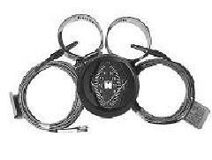
3.2Exhaust gas temperature
Agauge that we recommend on all Hirth two stroke engines is the Westach Exhaust Gas Temperature gauge
(EGT) as in figure 3.2.1. This gauge is a reliable measurement tool that measures the exhaust gases as they
exit the engine. A rich fuel/air mixture which can be caused by improper jetting, clogged air filter, improper
prop setting, will generally show up as a cooler temperature. A too lean mixture can be caused by an air leak
or fuel blockage, can result in overheating and engine seizure.
Figure 3.2.1 Westach Dual EGT 029.30
The proper location of the EGT probe on the exhaust manifold is extremely important. Mounting the probe
too close or too far from the piston will result in an incorrect reading.
If the engine is installed with one carburettor, the probe needs to be located in the centre of one of the
exhaust manifold ports 85mm from the exhaust outlet of the engine cylinder exhaust port. If the engine is
installed with two carburettors, each probe needs to be located in the centre of each of the exhaust manifold
port, 85mm from the exhaust outlet of the engine cylinder exhaust port. Install the probe before reinstalling
the manifold and make sure the probe will not touch the other side of the manifold wall.
The 50mm round EGT the gauge will mount from the front of the panel and will require a 52.388mm round
hole, a U bracket holds it in place from the rear.
The EGT gauges require probes which come with 100mm of lead. To install the probe, drill a 4.763mm hole
in the centre of the exhaust pipe at the recommended distance above. Install the probe into the hole, and
tighten up the clamp. As an option, manifolds are provided to suit the "bayonet probe" type. The terminal
cable can be lengthened to a maximum of 4.5 metres without affecting the accuracy of the instrument.
Route all wires away from the manifold and other heat sources. Support the wires every 300mm intervals,
using tie wire or similar. When going through firewalls etc, use rubber grommets to prevent damaging the
wiring. Do not route these wires with any wires from an AC source, such as a lighting coil, spark wires, tech
wires, etc. The EGT operates on .004 millivolts. Running near an AC source will result in incorrect
readings.
It is important that you verify the EGT readings by careful examination of the spark plugs. A reading on an
EGT of 1100 to 1200 degrees F should give a nice tan coloured spark plug. Lower readings should give
darker colours while higher readings grey/white colours.
|
  http://www.ultralightnews.ca/ Page 16 of 39
The Ultralight News - your one stop Ultralight News.
Once you have verified a spark plug colour and seen where your gauge reads with the proper colour then it is
now more important to watch for a CHANGE in the gauge reading from this "normal reading."
It is important to set your engine up for proper fuel to air mixture, your EGT gauge and probes can aid in
doing this. A lean mixture will run hotter on the EGT. A rich mixture will run cooler on the EGT but will
make increasingly less power. Ideally the highest EGT temps should come in at settings usually 5200 to 5800
rpm.
Reason for EGT temperature changes include:
Air intake leak.
Air fuel mixture too lean
Air fuel mixture too rich
Changes in density altitude
Changes in relative humidity
Changes in air temperature
Pre-ignition or detonation
Fault spark plug or ignition system
Improper prop load
Poor quality or grade of fuel
Improper fuel air ratio, plugged main jet, failed needle jet, or clip
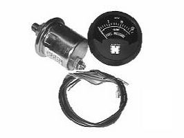
3.3Fuel Pressure
As mentioned previously, it is recommended to maintain a constant fuel pressure under all conditions.
Additional monitoring of fuel pressure by means of a fuel pressure gauge may also be considered. One such
suitable gauge is manufactured by Westach and is available for pressure of 16psi and 80psi.
Figure 3.3.1 Westach fuel pressure gauge 029.20/029.21
|
  http://www.ultralightnews.ca/ Page 17 of 39
The Ultralight News - your one stop Ultralight News.
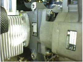
3.4Model Identification plate
The model plate is attached to the intake side on the upper part of the crankcase This also includes the serial
number of the engine and must be quoted should a warranty claim be required.
Figure 3.4-1 (Position of the Model Plate)
4Specifications ? F30E engine
Table 4 -1
Manufacturer Göbler-Hirthmotoren KG
Model F30E
Operating mode Two stroke
Number of cylinders Four boxer
Piston Capacity 1042 cm
3
Stroke Length 64 mm
Bore 72mm
Compression ratio 9.5:1
Performance 61 kW (83 HP) F30E specified with fans
RPM, max. 6500 rpm
Direction of revs Left, looking towards the drive shaft
Starter Electric Starter and/or Recoil Starter
Ignition System Electronic Characteristic Ignition, single or dual
Generator 250 W, 12 V
Sparkplugs B 8 HS (NGK) W2AC (Bosch), W 24 FS-U (ND)
Ignition Timing 16v. OT (at 2000 rpm)
0
Fuel injection 4 Bosch injectors, 4 Air filters
Cooling Fan Cooling, directly driven via poly flex belts Optional
Mixing 1:50
Fuel Premium unleaded, 95 Octane
Two Stroke oil Branded two stroke oil for hot (air-cooled) engines
Cylinder head temperature Max 280C/536F
00
Exhaust gas temperature max 680C/1256F
00
Fuel pressure min. 42 psi
Engine weight without exhaust System 42kg
Weight of exhaust system 10 kg
|
 http://www.ultralightnews.ca/ Page 18 of 39
The Ultralight News - your one stop Ultralight News.
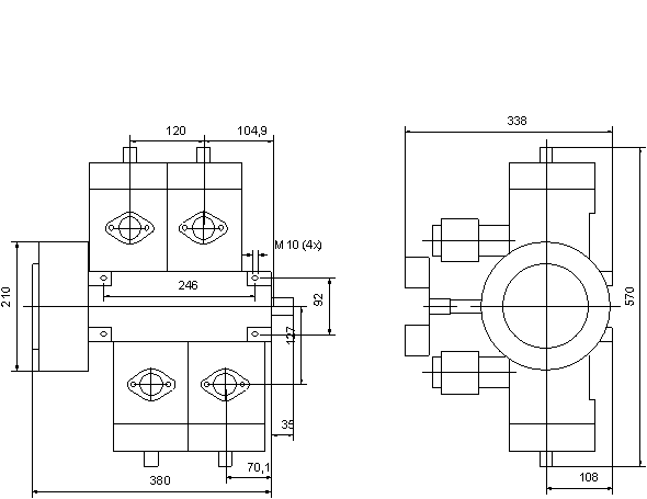
4.1Installation Drawing - F30E
|
    http://www.ultralightnews.ca/ Page 19 of 39
The Ultralight News - your one stop Ultralight News.
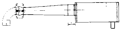
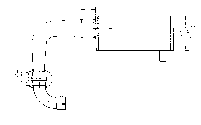
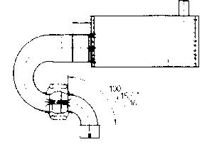
5Exhaust System
Detailed below are the three basic exhaust versions suitable for the F30E engine. It is extremely important to
note the distance where the diffuser is inserted into the silencer. On the F30E engine, the distance of "I" is
28mm therefore the diffuser MUST be inserted completely into the silencer then withdrawn 28mm.
1x 278 E19U Connection Bow
Ver. 1 1x 278 T19U Diffuser cone (straight) l = 28 mm
or Ver. 2 1x 278 T20U Elbow (90°) l = 28 mm
or Ver. 3 1x 278 T21U Elbow (180°) l = 28 mm
1x 278 E4U Silencer
Version 1 (Straight Version):
Version 2 (90° Elbow Version):
Version 3 (180° ElbowVersion):
|
        http://www.ultralightnews.ca/ Page 20 of 39
The Ultralight News - your one stop Ultralight News.
Please note, the performance specified for this engine will not be obtained if an exhaust variant is used which
differs from the three basic versions. As a result from such modifications, it is possible that damage may
occur to the engine. There will be no liability by Göbler-Hirthmotoren KG to provide any warranty for any
malfunction or damage incurred by such modifications.
5.1Exhaust parts and measurements
278 E4U Silencer Complete
Weight : 3,2 kg
278 E19U Connection Elbow
Weight : 0,6 kg
278 T19U Diffuser Cone, Complete
Weight: 1,5 kg
278 T20U Elbow 90°, complete
Weight : 1,4 kg
268 A11U Clamp
54.1
Spring
278 T21U Bow 180°, complete
Weight : 1,4 kg
278 H4U Ball Joint
Weight : 0,26 kg
|
 http://www.ultralightnews.ca/ Page 21 of 39
The Ultralight News - your one stop Ultralight News.
6Operation of the Engine
6.1General
It is important to observe the instructions provided in this chapter in order to maintain a safe and economical
operation of the engine.
USE ONLY THE PRESCRIBED TYPE OF TWO STROKE OIL AND THE PROPER GRADE
OF FUEL.
INSURE THAT FUEL IS MIXED IN THE CORRECT GAS/OIL RATIO. REMOVE THE FUEL
FROM THE CARBURETOR BOWLS AND FUEL TANK WHENEVER THE ENGINE IS NOT
GOING TO BE USED FOR AN EXTENDED PERIOD. AFTER A LENGTHY STANDDOWN,
REMOVE ANY LEFTOVER FUEL IN CARBURETOR BOWLS AND FUEL TANK BEFORE
OPERATING THE ENGINE.
TAKE CARE THAT THE AIR CIRCULATION IS SUFFICIENT TO COOL THE ENGINE AND
SUPPLY THE CARBURETORS.
INSURE THAT THERE IS NO OBSTRUCTION THAT CAN IMPEDE THE EXIT OF HOT
AIR.
ENSURE THAT HEATED EXHAUST AIR FROM THE COOLING SYSTEM IS NOT SUCKED
INTO THE CARBURETORS.
USE ONLY RESISTOR TYPE SPARK PLUGS AND RESISTOR PLUG CAPS.
ALWAYS ALLOW THE ENGINE A WARMUP AND COOL DOWN PHASE:
6.2Running in - Recommendation
Göbler-Hirthmotoren KG does not give explicit instructions for running in its engines, since the
nickel-silicium coating of the cylinder and the aluminium pistons do not have to wear to each other. The
engines are ready for full throttle from the time they are built if the maximum temperatures of the cylinder
head and exhaust gases mentioned earlier are not exceeded.
However, it would be wise when the engine is first started, to run the motor at half throttle and load (not over
4000 rpm) for the first hour of operation. Please note, the engine has been initially run at the factory to set the
electronic timing so it is possible when the engine is first started, there may be more smoke than usual. This
is generally due to excess oil possibly still in the engine during assembly and will reduce to normal after the
engine has been running for a couple of minutes.
6.3Initial Inspection
After the first 10 - 15 hours in operation or after a large service the following service tasks should be carried
out:
-Tighten the engine fitting screws as a safety measure
-Re-torque the cylinder head screws as a safety measure
-Tighten the sparkplugs as a safety measure
-Visual check (leakage, loose nuts/screws etc.)
Note:
It is recommended that the following inspection be carried out for safety reasons before each use of the
engine:
Starter (check connections, fitting and condition)
Carburettors (check connections, fixtures and condition)
Ignition system (check connections, fitting and condition)
Air cooling system (check fitting and condition; check fan belts for condition and tension)
Cylinder head (check connections, fitting and condition)
Cylinders (check fixtures and condition)
|
 http://www.ultralightnews.ca/ Page 22 of 39
The Ultralight News - your one stop Ultralight News.
Exhaust gas manifold (check fitting and condition)
Exhaust system (check fixtures and condition)
Sparkplugs and sparkplug leads (check fitting and condition)
Fuel system (check for leakage and dirty filter)
6.4Starting Procedure
The injection system has automatic cold start compensation.
First time in operation:
1.Turn on the ignition system.
2.Turn on the injection system.
3.Open the throttle valves fully.
4.Turn the injection system on a second time for a total of 10 seconds of purge to allow the system to fully
evacuate air from the system.
5.Close the throttle fully.
6.Engage starter to start the engine. Should the engine not start, you may need to open the throttle valves
slowly during start up.
Note: The starting sequence should be interrupted after a maximum of 20 seconds, if the engine doesn?t start.
After a short break repeat starting sequence.
7.As soon as the engine runs on it?s own, turn off the starter and keep engine running with 2-3 short burst
of acceleration.
8.Warm up the engine at 2000-3000 RPM under a light load
9.If the engine is warm, adjust throttle to idle
10.During and after the first operation you have to do the following test on the injection system:
Check the fuel lines and connections for leaks.
Check fuel lines for cracks and signs of rubbing.
Check electrical lines for secure connections and signs of stress.
Check throttle cable for smooth operation and security.
Check idle speed and adjust if necessary.
Exchange any damaged parts, and install new parts in accordance to proper installation procedures to
avoid damage.
6.5Starting the engine
Cold engine
1.Turn on the ignition system.
2.Turn on the injection system.
3.Start the engine with throttle fully closed. Should the engine not start under those conditions, open the
throttle slowly while starting the engine.
Note: If engine doesn?t start, stop the starting sequence after a maximum of 20 seconds. After a short
break, repeat starting sequence.
4.If engine fails to start after repeated attempts with above procedure. Advance throttle to full open
position. This will cause the injectors to spray at 100% for 1 second. Return throttle to closed position
|
 http://www.ultralightnews.ca/ Page 23 of 39
The Ultralight News - your one stop Ultralight News.
and repeat starting procedure. If engine fails to start do not repeat this step as engine will become
flooded.
5.As soon as engine runs on it?s own, turn off starter and keep engine running with 2-3 short accelerations.
6.Warm engine at 2000-3000 RPM under a light load.
6.6Operating condition of the engine
While the engine is running, the cylinder head temperatures and the exhaust gas temperatures should be
monitored. As long as the maximum-temperatures of the cylinder head- and/or exhaust temperature are not
exceeded, the engine can be run without a time limit in the set load range (also full load at maximum
performance). It is also recommended to monitor the fuel pressure during operation. Lack of fuel pressure
can lead to a loss of performance and cause the engine to fail.
Hot engine
1.Turn on the ignition system.
2.Turn on the injection system.
3.Start the engine with throttle slightly open. Should the engine not start under those conditions, open the
throttle slowly while starting the engine.
Note: If engine doesn?t start, stop the starting sequence after a maximum of 20 seconds. After a
short break, repeat starting sequence.
4.As soon as engine runs on it?s own, turn off starter and keep engine running with 2-3 short accelerations.
5.Warm engine at 2000-3000 RPM under a light load.
If the engine has a centrifugal clutch installed within the drive system, then the following should be observed
1.Warm up the engine at revs in which the centrifugal clutch is engaging firmly.
2.Warm up the engine at revs in which you can ensure that the centrifugal clutch is not engaging.
Since in this case the warming up revs are very low, the length of the warming up time should work
out appropriately longer.
Note:
If the warming up phase or running takes place at the level of rpm?s where the centrifugal clutch engages,
then increased wear on the linings, glazing of the linings or overheating of the clutch will result.
6.7Shut down the engine
Before the engine is switched off, it should be run for a minute in a load free condition at idling revs. Due to
the working fan, the cylinder head temperature should reduce. This procedure should always be followed,
since an engine that is switched off directly after a high load condition tends to overheat.
1.Turn off the injection system.
2.As soon as the engine quits, turn off the ignition system.
Comment: You must remember to turn off the ignition system, because it may cause damage to the
ignition electronics. Furthermore, by touching the primary side, the remaining voltage may
lead to a shock.
6.8Adjustments
The system is adjusted at the factory. The idle was adjusted to 1700-1800 RPM without any load (without
propeller and gearbox). The throttle valves and throttle position sensor are synchronised to each other and
cannot be changed.
|
  http://www.ultralightnews.ca/ Page 24 of 39
The Ultralight News - your one stop Ultralight News.
Attention: Don?t twist the adjusting screw (Figure 6.8-1 Position4) as this is set at the factory.
The only required adjustment is the idle. To do that you must please do the following:
1.Engine must be warm.
2.The load, which impacts the engine in idle position, has to be installed (propeller etc.)
3.The throttle cable must have a 2-4mm or 0.078-0.156 inches play while in idle position so the idle stop
screw is adjacent to the throttle stop (Figure 6.8-1Position 3).
An idle RPM is chosen so that the engine runs smooth and secure (recommendation: 1200-1800 RPM) To
make any necessary adjustment, turn the idle adjust screw in or out (Figure 6.8-1Position 4). Clockwise turn
increases RPM, counter clockwise decreases RPM.
Tip: Open throttle valves in order to better access adjustment screw.
Figure 6.8-1: Throttle body.
6.9Starting Procedure
Secure the fuel supply (fill the tank, open the fuel cock,...)
If the engine is cold, engage the choke(s).If the engine is warm or hot do not engage the choke.
Move the throttle lever into a fast idle position.
Switch on the ignition system (ON-Position of the ignition switch)
Start the engine (Activate starter maximum 10 seconds)
When the engine has started, reduce the choke slowly to the off position and apply a small amount
of throttle.
Allow the engine to warm up at a ¼ load or 3000 rpm for about 3 minutes.
The engine should now be ready for operation.
Please note: If the engine has a centrifugal clutch installed within the drive system, then engine should be
run with the clutch firmly engaged to avoid unnecessary wear of the clutch lining.
6.10Operating condition of the engine
While the engine is running, the cylinder head temperatures and the exhaust gas temperatures of both
cylinders should be monitored. So long as the maximum temperatures of the cylinder head and/or exhaust
temperature are not exceeded, the engine can be run without a time limit in the set load range (also full load
|
|
http://www.ultralightnews.ca/ Page 25 of 39
The Ultralight News - your one stop Ultralight News.
at maximum performance). It is further recommended during operation to monitor the fuel pressure. Lack of
fuel pressure will lean the fuel mixture and lead to a loss of performance and cause the engine to fail.
6.11Powering down the engine
Before the engine is switched off, it should be run for a short period at fast idling revs. This will allow the
cooling system to reduce the temparature of the engine gradually without stressing any components and
overheating.
|
 http://www.ultralightnews.ca/ Page 26 of 39
The Ultralight News - your one stop Ultralight News.
7Maintenance
7.1General
This chapter contains the necessary directions to allow technically qualified persons to carry out the smaller
repairs and inspections such as:
Periodic inspections of the engine
Maintenance of engine parts
Troubleshooting
7.2Tools, special tools and torques
The specifications and sizes of tools are given according to the metric system and can be procured
commercially in specialty shops.
Tools:
Description Size Description Size
Adjustable wrench 7 Adjustable wrench 8
Adjustable wrench 10 Adjustable wrench 13
Hexagon socket screw key 3 Hexagon socket screw key 4
Hexagon socket screw key 5 Hexagon socket screw key 6
Sparkplug wrench Sparkplug wrench 20.6/20.8
Torque wrench 0 -100 Nm Screwdriver
Special Tools:
The special tools are available for purchase under the indicated G.-H. numbers from AATI Pty Ltd or a Hirth
distributor.
Description GH-Number
Magnetic wheel - extractor W 138
(Piston ring clip (Piston ?aid in assembly) W 108/15
Torque settings
Description Initial Torque Description Initial Torque
M4 x 2.8 ? 3.3 Nm M5 x- 4 ?4.4 Nm
M6 x 9 -11 Nm M8 x 23-28Nm
M16 x 70-80 Nm Sparkplug 16 Nm
|
 http://www.ultralightnews.ca/ Page 27 of 39
The Ultralight News - your one stop Ultralight News.
7.3Maintenance rate - Daily inspections
Before operating the engine, a thorough daily inspection should be carried out. Observe the following points:
1.Air filter - check condition and installation
2.Starter - check condition and installation
3.Ignition system - check condition, fastening, and connections
4.Fan housing - check condition and installation
5.Fan - check condition and fastening
6.Fan belt - check condition and belt tension
7.Cowling - check overall condition and the fasteners
8.Crank case and cylinders - check for leaks overall condition of installation
9.Spark plug caps - check condition and the connections
Periodic Inspections
Inspection Rate
25 h 100 h 500 h
Cooling
Airway: check for free flow and freedom from pollutants
XX
X
Baffles: check for damage and cracks
XX
X
Check fan belts for deterioration and damage
X
Carburettors
Clean the air filters
XX
X
Check the throttle body setting
XX
X
Fuel system
Clean the fuel filters
XX
X
Check fuel lines and ?connections
XX
X
Ignition
Clean the spark plugs
XX
X
Check the sparkplug air gaps
XX
X
Exhaust system
Check for firm fitting and deterioration
XX
Check outlet ports for carbonisation X
X
|
 http://www.ultralightnews.ca/ Page 28 of 39
The Ultralight News - your one stop Ultralight News.
7.4Fuel Injector Maintenance/Service intervals
The injection system is, except for the disciple components, maintenance free. The following maintenance
work should be exercised.
No. Description Interval
After installation Then every
(hours)
(hours)
1510 25
1Check fuel system for damaged lines
XXXX25h
2Check electrical wiring for damage
XXXX25h
3Check the condition and function of the throttle cable
Each startup
4Check the throttle cable for damage and lubricate
XX
X50h
5Clean air cleaner or replace if necessary
X25h
6Check fuel filter for contaminants and replace if necessary
before replacement interval (change fuel filters together)
X
50h
7Check screws and nuts on the fuel pump, TBI, airfilter, cable XXXX50h
fastenings etc
The following parts must be replaced
No. Description Replacement interval
1Inlet fuel filter
All 200h
2Outlet Fuel Filter
All 200h
3Air Filter
All 250h
4Fuel Pump
2000h
5Injector valves
All 2000h
Long-term inspections
Inspection Rate 25 h 100 h 500 h
Cooling
Check cooling flow paths are free and clean
X
X
X
Check air guiding plates for deterioration and tears
X
X
X
Check fan belts for deterioration and damage
X
TBI
Clean the air filters
X
X
X
Check the throttle synchronisation
X
X
X
Fuel system 25 h 100 h 500h
Clean the fuel filters
X
X
X
Check fuel lines and ?connections
X
X
X
Ignition
Clean the spark plugs
X
X
X
Check the sparkplug air gaps
X
X
X
Exhaust system
Check for firm fitting and deterioration
X
X
X
Check outlet ports for carbonisation
X
X
|
 http://www.ultralightnews.ca/ Page 29 of 39
The Ultralight News - your one stop Ultralight News.
8Replacement of Parts
The parts listed in Table 3.3-1 should be replaced after the specified number of operating hours.
Consideration should be given to componets which may show signs of premature failure and replaced
accordingly.
Table 7-3-1
The abbreviation ?Single? means single ignition and ?Dual? represents dual ignition.
Qty Description Part number Operating Hours
4Sparkplug Single 023.29 50
8Sparkplug Dual 023.28 50
1-8 Sparkplug cap 024.22 100
4Piston set 014.72 1000
1Crankshaft F301 AA1U 1000
4Cylinder head single ignition Cylinder 1 = F302A30U 1000
Cylinder 2 = F302A25U
Cylinder 3 = F302A21U
Cylinder 4 = F302A24U
2Cylinder head dual ignition Cylinder 1 = F302B31U 1000
Cylinder 2 = F302B28U
Cylinder 3 = F302B23U
Cylinder 4 = F302B24U
2Cylinder 272K1 1000
2Injectors 277EA3 - Bosch 1000
2Air filter 277D6U 100
8.1Inspecting the air filters
To remove the air filters, undo the three M6 bolts securing the rain shield and lift off each carburettor.
Separate and remove the air filter. Wash out the air filter with fuel and then dry with compressed air from
inside to out. Reinstall or replace if necessary.
8.2Inspecting the fuel lines
Check the fuel lines between the diaphragm pump, carburettors and fuel tank for leakages and/or other
damage. Replace leaking and/or damaged fuel lines.
8.3Inspecting pulsation lines
Check the pulsation line between the vacuum nipple on the crankcase and the pulse connection of the fuel ?
diaphragm pump for leakage and/or other damage. Replace the leaking and/or damaged pulsation line.
8.4Spark plugs and sparkplug leads
It is recommended that the spark plugs be checked one after the other to avoid mixing up the sparkplug leads
and their connecting positions.
8.5Inspecting the condition of the sparkplug leads
Remove the sparkplug leads and check the contact socket inside for corrosion. Check the SAE-contact (the
screwed on contact hood) of the sparkplug for corrosion or "deposits". If there is corrosion or "deposits",
replace the sparkplug lead and SAE- contact of the sparkplug (usually here the sparkplug would be
completely exchanged - see next paragraph).
|
 http://www.ultralightnews.ca/ Page 30 of 39
The Ultralight News - your one stop Ultralight News.
8.6Installing and removing sparkplugs
To uninstall the sparkplug, remove the sparkplug lead. Loosen the sparkplug with the sparkplug wrench and
unscrew it.
Before installing the new or still serviceable sparkplug, the air gap (0.8 mm) is to be checked with a feeler
gauge and adjusted as required.
Screw the sparkplug into the cylinder head with a sparkplug wrench and torque to the correct setting.
8.7Condition of the sparkplug
The spark plug should have a dry bright brown colour tone on the central electrode, the insulator of the
central electrode and the earth side of the case. If the colour tone changes to a bright very dry grey, the
engine is running very hot and the mixture is too lean. Where there is a wet dark brown to black colouring,
the engine is running with too thick a mixture. In both cases, AATI Pty Ltd or your Hirth distributor should
be contacted.
Check the sparkplug central electrode and earth strap for corrosion (burning). If signs of burning are
detected, the sparkplug should be replaced. For more information on how to read sparkplugs, go to the
maintenance pages on the http://www.ultralightnews.ca/web site.
9Fans
It is necessary that the opening for the fan remain unobstructed. Only sufficient flow of fresh air and
satisfactory operation of the fan can guarantee proper cooling of the engine.
9.1Remove and assembling the air cowl
To remove the air cowl, remove the sparkplug leads and unscrew the sparkplugs. Mark the position of the
sparkplug leads. Remove both screws which secure the cowl to the cylinder heads. These are directly below
the spark plug access holes in the cowling. Remove the two screw which attach the air cowl clamp to the fan
housing. You should be able to leave the clamp attached to the air cowing by the M6 bolt. Remove the
housing from the engine To install the air cowl, reverse the process used for removal. Should there be any
damage to the air cowl should be replaced immediately.
9.2Remove and assembling the fan housing
To remove the fan housing, unscrew the nylex nut of the adjustable cam centre of the fan wheel so that the
polyflex belt of each fan is without tension. Remove the four front screws of the fan housing and pull the
shroud off along the axis of the adapter sleeve. After the fan housing slips off the adapter sleeves, push the
fan housing downward and take the polyflex belts off the pulley. Replace any suspect or damaged belts. To
install the fan housing, reverse this process in logical order. Turn the adjustable cam centre of each fan to a
suitable tension.
10Cylinder head
The cylinder heads are manufactured from a special aluminium alloy which permits a maximum temperatures
of 280C. If the metal is overheated (ca. 300° C), the material looses hardness. This loss in hardness leads to
0
leakages in the seal surface between the cylinder head and the cylinder. Tightening the cylinder head screws
will have no effect. The cylinder head must be replaced.
10.1Cylinder head removal and installation
To remove the cylinder head, remove the spark plug caps, the spark plugs, and the fan housing, as described
above. Loosen and unscrew the eight cylinder head screws with a hexagonal socket wrench. Mark the
position and placement of the cylinder heads, then remove cylinder heads. To install the cylinder heads,
reverse the process, tightening the cylinder head screws lightly and first, then applying the prescribed torque
values using crossway technique.
|
|
http://www.ultralightnews.ca/ Page 31 of 39
The Ultralight News - your one stop Ultralight News.
10.2Checking the condition of the cylinder head
Check the seal of cylinder heads and cylinders for places on which exhaust gas has blown through. These
places can be recognized by black lines over the seal and burned residue on the cooling fins. If this is the
case, the cylinder head must be immediately replaced. Check the indentation on the cylinder head for the
black residue. If present, remove it and eventually change the type of oil used.
|
|
http://www.ultralightnews.ca/ Page 32 of 39
The Ultralight News - your one stop Ultralight News.
11Trouble Shooting (general)
11.1Engine Does Not Start or is Difficult to Start
Cause: Lack of fuel
Solution: Insure fuel switch is on
Insure fuel filter is clean
Insure that fuel is in the tank
Cause: Defective or discharged battery
Solution: Replace battery
Charge the battery
Cause: Lack of compression on one or both cylinders, due to a loose spark plug or a defective
piston, piston ring, cylinder head, or cylinder:
Solution: Tighten spark plug to prescribed torque, or ship engine to the manufacturer or an
authorized Hirth service centre
Cause: - No spark or weak spark due to defective spark plug, spark plug cap, or a defective ignition
Solution: Replace spark plug, spark plug cap, or have the manufacturer or an authorized Hirth
service centre replace the defective ignition
11.2Engine Runs Rough, Uneven, and with Insufficient Power
Cause: Dirty air filter
Solution: Clean or replace air filter
Cause: Dirty or defective spark plugs
Solution: Clean or replace the spark plugs
Cause: Dirty fuel filter
Solution: Clean or replace fuel filter
Cause: Fuel mixture has too much oil in the gasoline
Solution: Empty tank and fill with fuel of the proper mix
Cause: Defective sparkplug caps
Solution: Replace the spark plug caps
11.3Excessive Cylinder Head Temperature
Cause: Fan belt too loose or defective
Solution: Tighten fan belt or replace
Cause: Defective fan
Solution: Replace the fan
Cause: Defective shroud
Solution: Replace shroud
Cause: Insufficient cool air reaching the blower Solution: -Install blower so that fresh air gets to
the blower unhindered
|
|
http://www.ultralightnews.ca/ Page 33 of 39
The Ultralight News - your one stop Ultralight News.
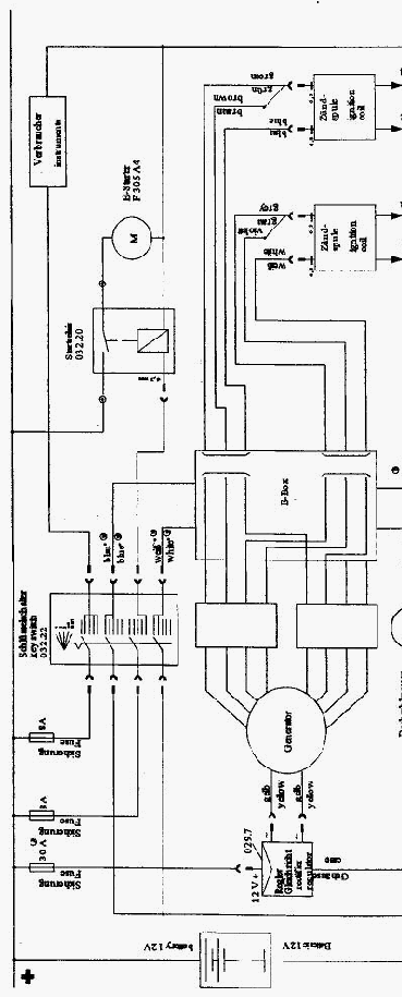
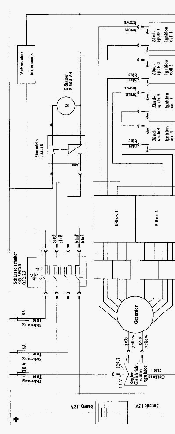
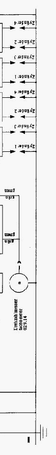
12Wiring Diagrams
The following two diagrams for the single- and dual-ignition systems show the PVL ignition system.
These wiring diagrams should be understood as suggestions for the periphery of the ignition system.
Cross section in general: 1.5mm²
Cross section from/to Electric Starter: 16 mm²
|
   |
   |
 |
 |
 |
 |